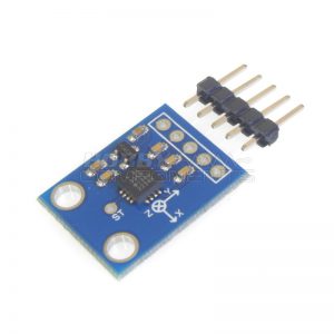
ADXL335 Accelerometer measures acceleration or responds to acceleration, detecting when something starts to move or stop. It can even detect how something is oriented with respect to the Earth’s surface. They come in various types and different number of axes they can sense. Here, we’ll be using 3 axes accelerometer, sensing acceleration in all three directions. It is small and a low power module.
Soldering
You might have to solder the breakout board. What you solder depends on how you’re going to use it. You’ll need straight headers for the breadboard purpose.

How Does It Work ?

Accelerometers use different technologies to measure acceleration. In embedded electronics, it is MEMS ( Microelectromechanical Systems ). Some parts inside the sensor are freely moving and change their internal resistance to output a different voltage. The ADXL module is very susceptible to vibrations and might disturb the readings. It measure acceleration forces which might be static like the force of gravity and by measuring the static acceleration due to gravity, you can find the angle the device is tilted with respect to the earth. They are used in laptops to protect hard drives from damages ( See tutorials on embedded systems ). Tiny plates inside the sensor when subjected to acceleration change the distance between them , changing capacitance , and hence voltage. Acceleration is measured with the help of polysilicon suspended above silicon wafer with the help of polysilicon springs.

You can find the Sparkfun Datasheet from here : Datasheet
Parts Required
Fritzing Board View
I have created a really simple Fritzing sketch.

Pin Label
- VCC : To be connected to 5V on the Arduino Board. Some of the Accelerometers have pin label of 3.3V. In that case, connect to the 3.3V pin on the Arduino.
- GND : To be connected to the Ground ( GND ) pin of Arduino.
- X Pin : Measures acceleration in the X direction ( Reference of frame mentioned on module ). It is connected to Analog Pin A0 on the Arduino.
- Y Pin : Measures acceleration in the Y direction. It is connected to Analog Pin A1 on the Arduino.
- Z Pin : Measures acceleration in the Z direction. It is connected to Analog Pin A2 on the Arduino.
- ST : Some modules include the ST pin which is Self-Test to verify sensor functionality and is connected to GND. We have not used the pin here.
Code
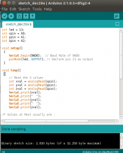
Upload the following on the Arduino IDE :
int led = 13;
int xpin = A0;
int ypin = A1;
int zpin = A2;

void setup()
 {
    Serial.begin(9600);  // Baud Rate of 9600
    pinMode(led, OUTPUT); // Declare pin 13 as output
 }

void loop()
 {
    // Read the 3 values
    int xval = analogRead(xpin);
    int yval = analogRead(ypin);
    int zval = analogRead(zpin);
    Serial.print(xval);
    Serial.print("  ");
    Serial.print(yval);
    Serial.print("  ");
    Serial.print(zval);

/* Values at Rest usually are :

   X ~ 330
   Y ~ 330
   Z ~ 440

However, you might need to test and calibrate your module  */

if(xval < 310 || xval > 350 || yval < 310 || yval > 350 || zval < 380 || zval > 460)
// Taking a margin of +/- 20
 {
    digitalWrite(led, HIGH); // Light up the LED if there is deviation from the set values
    delay(300);
    digitalWrite(led, LOW);
 }

delay(50); // Time for sensor to measure next incoming data

}

Final Comments
One key factor used in the tutorial was Analog to Digital Conversion ( ADC ). The Sensor reads analog values which are converted to digital for the Arduino. I’ll discuss the concept of ADC’s in the next tutorial which is even a main point of discussion on the BeagleBone Black. Thank you for reading the tutorial. If you have any questions feel free to ask in the comments below.


I’m very happy to discover this page. I want to to thank you for your time due to this wonderful read!! I definitely enjoyed every little bit of it and I have you saved to fav to look at new things on your website.