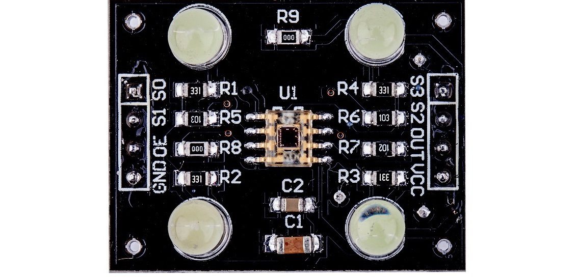
TCS-3200 Color Sensor is a programmable Color Light to Frequency Converter Module which can detect and measure nearly a limitless range of visible colors. It has an array of photo detectors, each with either a red, green, blue or no filter. The filters of each color are distributed evenly throughout the array to eliminate location bias among the colors. Internal to the device is an oscillator which produces a square-wave output whose frequency is proportional to the intensity of the chosen color. If you are using Arduino UNO, just change the pins and you are good to go!

Overview
- Square Wave : Is a non-sinusoidal wave form ( not pure sine waves ) in which amplitude alternates at a steady frequency between fixed minimum and maximum values, with the same duration at minimum and maximum.

- Electronic Oscillator : Is an electronic circuit that produces a periodic, oscillating electronic signal, often a sine or a square wave.

How does it work ?
The sensor senses color light with the help of 8 x 8 array of photo-diodes. It then uses a Current to Frequency Converter to convert the readings into a square wave with a frequency directly proportional to the light intensity. Finally, the Arduino Mega reads the square wave output and gets the result for the color.

The photo-diodes have 3 different sensors color filters. 16 of them have red filters, another 16 have green filters, another 16 have blue filters and the other 16 are clear with no filters.

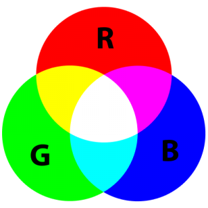
According to the RGB color model, a broad array of colors is produced by adding red, green, blue in different ways.

Each 16 photo-diodes are connected in parallel, so using the two control pins S2 and S3 one can select which of them will be read. For example, if we want to detect green color, we can just use the 16 green filtered photo-diodes by setting the two pins to high logic level according to the table. The sensor has two more control pins, S0 and S1 which are used for scaling the output frequency to three different present values of 100%, 20% or 2%.

Parts Required
Pin Wiring
Sensor Pin Arduino Pin
     VCC                     5V

     GND                     GND

      S0                     4

      S1                     5

      S2                     6

      S3                     7

      OUT                    10
Schematics
Connect the given module as per the above pin wiring instruction. Don’t worry if you’re using a different micro-controller. Just replace the pins mentioned above.

Code
int S0= 4; // S0 connected to Arduino pin 4
int S1= 5; // S1 connected to Arduino pin 5
int S2= 6; // S2 connected to Arduino pin 6
int S3= 7; // S3 connected to Arduino pin 7
int senseout= 10; // Out connected to Arduino pin 10
int frequency=0;

void setup()
{
   pinMode(S0, OUTPUT);
   pinMode(S1, OUTPUT);
   pinMode(S2, OUTPUT);
   pinMode(S3, OUTPUT);
   pinMode(senseout, INPUT);

   digitalWrite(S0, HIGH); // Output Frequency Scaling set to 20%
   digitalWrite(S1, LOW);  // because there is no filter (clear) initially
   Serial.begin(9600); // Baud rate set to 9600
}

void loop()
{
    // Red filters set to be read
    digitalWrite(S2, LOW);
    digitalWrite(S3, LOW);

    // Reading the output frequency

    frequency = pulseIn(senseout, LOW); // PulseIn reads a pulse (HIGH or LOW). Look here : StackExchange
    frequency = map(frequency, 25,72,255,0); // Remaping as per the RGB Model

    Serial.print("R= ");
    Serial.print(frequency); // Printing red color frequency
    Serial.print("  ");
    delay(100); // delay of 100 milli seconds

    // Green filters set to be read

    digitalWrite(S2, HIGH);
    digitalWrite(S3, HIGH);

    frequency = pulseIn(senseout, LOW);
    frequency = map(frequency, 30,90,255,0);

    Serial.print("G= ");
    Serial.print(frequency);
    Serial.print("  ");
    delay(100);

    // Blue filters set to be read

    digitalWrite(S2, LOW);
    digitalWrite(S3,HIGH);

    frequency = pulseIn(senseout, LOW);
    frequency = map(frequency, 25,70,255,0);

    Serial.print("B= ");
    Serial.print(frequency);
    Serial.println("  ");
    delay(100);
}
Final Thoughts
The module has a strong anti-interference ability with high resolution conversion of light intensity to frequency. Do share what you did with this sensor!
I hope you found the guide useful. Let me know your project ideas by dropping a comment below.


