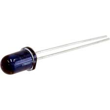
GP2Y1010AU0F or Sharp PM2.5 Dust Sensor consists of an Infrared Emitting Diode and Phototransistor ( which we are going to discuss shortly ) which detects the reflected light of dust in air and is efficient in detecting fine particles. It is compact with low consumption current ( max of 20mA ). It is commonly used in Air Purifiers, fire alarms, etc. Typical operating voltage is 4.5V-5.5V ( Max 7V ).

Overview
- Phototransistor : When we apply a potential difference across an LED, an electrical current will pass through it which will cause it to emit light. Reverse of it would be shining light on to an LED resulting in a current flow in the opposite direction as before and a potential difference is measurable across it. This setup allows LED to detect light. Following shows a simple experiment in which I used my torch and you can observe a potential difference across the LED when I shine light ( LED is shining due to torch light ).
 Also, there is a tiny current passing through the LED. To use this setup to detect light in our sensor we need to amplify it with a Transistor. Hence, this setup of a Photodiode + Transistor is called a Phototransistor. The Phototransistor used in the Dust Sensor system is an Infrared sensitive Phototransistor allowing Infrared light to penetrate.
- Infrared Emitting Diode : An Infrared emitter is a source of light energy in the Infrared spectrum which transmits information from one device to another.

How does it work ?
As per the above description, the Infrared Emitting Diode and Phototransistor are diagonally arranged to allow it to detect the reflected light of dust in air. The principle of dust detection is mentioned in the given datasheet : Dust-Sensor-Datasheet. As mentioned in the datasheet, the resistor and capacitor is required for pulse drive of the LED.

Parts Required
- 1x Dust Sensor
- 1x 150 Ohm Resistor
- 1x 16V 220uF Capacitor
- 1x Arduino UNO
- 1x Breadboard
- Jumper Wires
Dimensions and Terminal Connections

Fritzing Sketch


Code
int Dust_Analog = 0; // Arduin Pin A0
int Dust_Pin = 7;

float Dust_Voltage = 0;
float C_Voltage = 0;
float Density_Dust = 0;

void setup()
{
  Serial.begin(9600); // Baud Rate
  pinMode(Dust_Pin,OUTPUT);
}

void loop()
{
  digitalWrite(Dust_Pin,LOW); // LED gets powered on
  delayMicroseconds(280); // The output value to be measured 0.28ms after the LED turns on ( given in datasheet )

  Dust_Voltage = analogRead(Dust_Analog); // Read the raw value

  delayMicroseconds(40);
  digitalWrite(Dust_Pin,HIGH); // LED gets turned off
  delayMicroseconds(9680);

  C_Voltage = Dust_Voltage * (5.0 / 1024.0);
  Density_Dust = 0.17 * C_Voltage - 0.1;

  Serial.print("Raw Signal Value : ");
  Serial.print(Dust_Voltage);

  Serial.print(" - Voltage: ");
  Serial.print(C_Voltage);

  Serial.print(" - Dust Density: ");
  Serial.println(Density_Dust); // mg/m3

  delay(1000);
}
Upload the code in Arduino IDE and keep the Baud Rate at 9600. To install Arduino IDE, visit : arduino.cc
Output
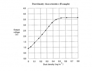
According to the datasheet, the dust density characteristics of GP2Y1010AU0F are given below :

Final Thoughts
For an experimental basis, try plotting the dust density values on Processing. Check out my previous Processing tutorials to get hands on Processing. Thank you for visiting the website. In case of any doubt, feel free to ask.


Thanks for the post!